I’ve been an amateur radio operator since 2001 and a short wave listener for a number of years before that. I’ve always been intrigued by long distance communications on the HF bands and enjoy communicating with stations from around the globe. I also like operating vintage AM tube gear as well. There’s nothing like bringing an old boat anchor back to life and getting it on the air. I’ve restored a number of vintage radios over the years, but recently got the homebrewing bug.
For years I used a WRL Globe Scout 680 on the 20 and 40 meter AM windows. This Novice rig from the 50s works fine, but it does leave something to be desired in the modulation department. It uses Heising modulation, and is only able to do at best 80% modulation. I also noticed some nonlinearity in the RF envelope. This prompted me to take the plunge into home-brewing.
I purchased a copy of the ARRL 26th edition, 1949 “The radio amateur’s handbook” and started reading from page 1. Although I’m not a stranger to electronics per say, I had never built anything using vacuum tubes. I had to start with the basics of how vacuum tubes work. After getting a basic understanding of tube theory, I started experimenting with simple Class A1 triode amplifiers. After successfully getting a simple amplifier working I began experimenting with oscillators. It was at this point that I decided to go all out and try to build a plate modulated AM transmitter.
I’m not going to say that this project was easy because it wasn’t. I had no help from an Elmer so I had to work through all issues on my own which took time. In total, I spent about 2 months on this build. The result is a 40 and 80 meter 20 watt high level plate modulated AM transmitter. It uses a pair of 6L6GC tubes in Class AB1 push-pull generating between 15 and 20 watts of audio power, high level plate and screen modulating a 6146. I like to add screen in the description since you have to modulate both the plate and screen of a Pentode to reach 100% modulation. The speech amplifier is a 6AU6 providing 155 gain followed by a 12AU7 configured as a self-balancing phase-inverter. This stage drives the 6L6GC modulators. The oscillator is a 2E26 configured as an Electron-Coupled Colpitts crystal Oscillator, which is capacitance coupled to the modulated RF amplifier. I use a Pi tank circuit to couple the output signal to the antenna.
Nothing fancy, it’s a standard 1940s design. It does sound good on the air though! I have received excellent signal reports from every station I’ve talked to with this rig. I completed the build by adding a face plate and finishing it off using Hammered vintage pewter paint. Here is a photo of the rig. The microphone used is a D-104.
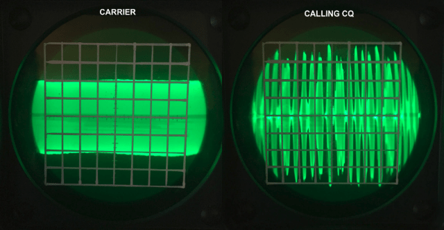
Here is an example of how the rig looks on the RF scope. It can easily modulate to 100% and then some if I’m not careful.
For those interested, here is the schematic. This started out as a blank sheet of paper and a goal. Build a transmitter from scratch that could be used to talk around the world with. I can say that I’m well on my way to the “around the world” part. I’ve already made contacts with stations across the United States and Canada. Now we just have to get more guys across the pond into vintage AM gear so that we can talk to them!
SAFETY WARNINGS
This project involves LETHAL power supply voltages. You must use great care when working with this circuit. Never forget that death is a permanent condition! Any homebrew project like this might involve troubleshooting a live circuit. If you don’t feel comfortable working with high voltages, then you should either forget about messing with tube-type equipment, or get friendly with a local ham who is experienced with this stuff and ask them to assist you and teach you what you need to know (this person is known as an “Elmer”, and every ham, new and old, should have at least one!). I recommend the latter. Never be afraid to ask for help! It’s much better to feel stupid for asking than to BE stupid and get yourself killed because you didn’t ask!
If you have any questions please leave a comment or drop me an email.
73’s
Joel
W4GON


Hi Joel, Interesting project you have here.
I see you changed a MOPA for CW from the ARRL book into a AM transmitter.
My experience is that A MOPA AM modulated as you did produces no ‘hifi’ sound if I MAY exaggerate what I experienced. The cause is the signal form the oscillator in a MOPA produces no small positive pulses. It produces very wide positive pulses and small negative pulses to the PA.
That results in distortion of the voice an to high screen grid current. I see you solved the screen grid issue through limited screen current by Lowering the voltage of the PA.
Can you elaborate on this isssue?
Greetings from Holland,
Koos
Hi Koos,
It has been a number of years since I was in the weeds building this rig so the details around some of the things I did is a bit fuzzy. Regardless, I don’t claim that this design is capable of making HiFi audio. It does sound good on the air and I have received many compliments on audio quality with it. I have switched between it and a Flex5000 set up for making good AM sound and the other side usually can’t tell the difference between the two. While building it I did change the PA voltage multiple times and messed around with the screen resistor value along with a bunch of other things to try to get it dialed in. I just can’t recall the details anymore! Ha
At the end of the day this is a simple 1940s design and it works well enough to chat with the AM crowd.
Joel
Hi Joel. Thanks for the schematic! I am at a similar stage as you were. I recently built my first class A transmitter with a single 6L6GC final, and I am looking to upgrade. This looks like a great second project.
My question is in regards to T1 in your diagram. Having only experience in Class A, I am not familiar with transformers. Can you provide a part number and maybe a brief explanation of this transformer? I really appreciate it. Thanks!
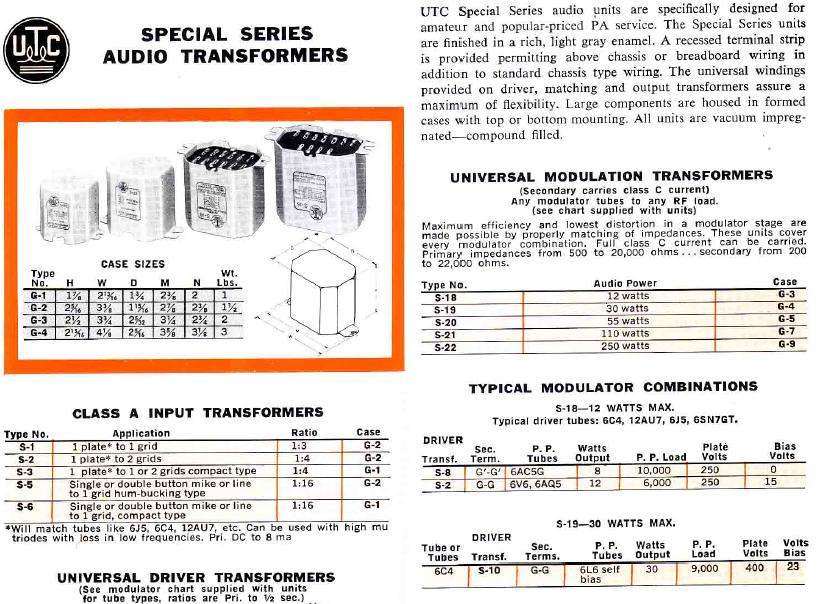
Hi Dave, and congratulations on your transmitter build! Sure thing, T1 in my schematic is a UTC Model S-19 universal modulation transformer. It can handle up to 30 watts of audio power and since my modulator is generating around 15 watts of audio power it’s a good match. I found the transformer on Ebay and highly recommend a universal mod transformer if you are experimenting and trying to settle on a design as you go. This is because these transformers come with a set of primary and secondary taps that depending on how they are wired can set the primary impedance from 500 to 20Kohms and your secondary from 200 to 22Kohms! You can find the impedance which your push-pull modulators will present to the primary of the mod transformer in the tubes datasheet. The 6L6GC is around 9Kohms or so at the rated plate voltage. Now where it gets tricky and where the UTC S-19 was so valuable in my project is when settling on the secondary impedance value for the transformer. To get the modulating impedance or load resistance presented to the modulator by the modulated RF amp the formula is: Eb/Ip*1000, where Eb is the DC plate voltage and Ip is the DC plate current (in mA) of the RF amp (6146 in my case). You make the measurement with no modulation. During the build process my final plate voltage changed three times. Therefore, the modulating impedance of the RF amp changed three times, and by a few thousand ohms or more at that! Therefore, if I had just picked up any old mod transformer I could have been way off in matching the modulator stage to the modulated RF stage. This should give you an idea of what the S-19 or similar universal mod transformer is all about: .
.
Keep me posted on your high level plate modulated AM transmitter. It really is an achievement to roll your own and very gratifying to get on the air with your handy work. Maybe I could be your first contact with it!
73s
Joel
W4GON